How 3D Roof Drawings Help Roofing Contractors Win More Bids
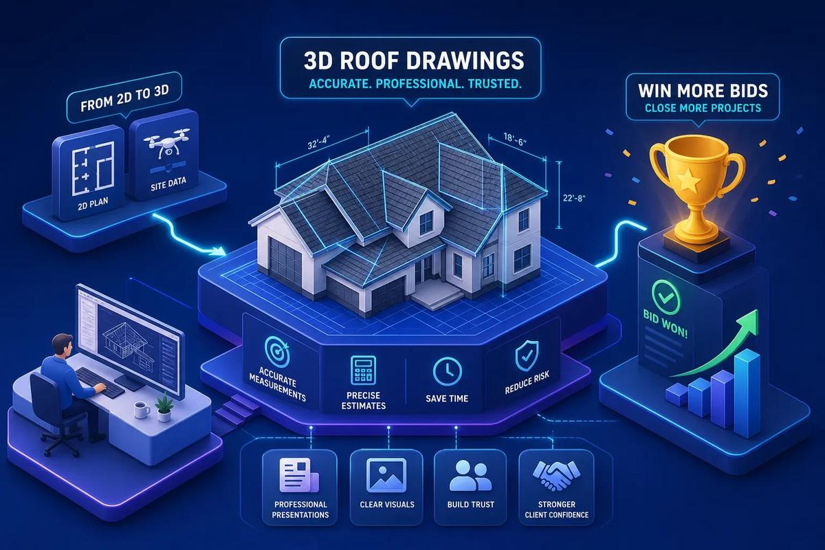
Many contractors who win more roofing bids combine accurate measurements with strong visual proposals and competitive pricing. A 3D roof drawing makes that combination possible, giving you accurate plane areas, slope-adjusted square counts, and ridge and valley linear footage confirmed before a single bundle of shingles gets ordered. The workflow around that drawing is what separates fast closers from contractors still emailing handwritten numbers two days after a site visit.
When you pair a reliable 3D roof model with a clean, itemized proposal delivered the same day as the inspection, you've built a sales process that compounds over time. This guide covers the full loop: which tools fit different project types, how to convert a 2D plan into a usable 3D model, how pitch translates into real material quantities, what data to pull from the model for a bid, the mistakes that quietly corrupt takeoff data, and how platforms like URBLD close the distance between a finished estimate and a signed contract.
Key Takeaways
- Geometry drives accuracy: A 3D roof drawing measures every plane, hip, valley, and ridge digitally, removing the compounding errors of visual pitch estimation and manual square counting.
- Pitch multipliers change everything: A 6:12 roof has a pitch factor of 1.118, meaning a 2,000 sq ft footprint produces 2,236 sq ft of actual roof surface before waste is added.
- Tool choice depends on project type: Aerial measurement platforms work well for residential reroofing; full CAD tools like SketchUp or Revit fit complex commercial projects.
- Waste factors vary by complexity: Simple gable roofs require 5–10% waste allowance; roofs with multiple hips, valleys, and dormers often require 15–20% or more.
- Proposal speed affects close rates: Same-day or on-site delivery consistently outperforms delayed estimates. Contractors who track close-rate data consistently report 20–30% higher close rates for same-day proposals.
- Manual re-entry is the hidden bottleneck: The biggest gap in most estimating workflows is copying model data into a separate proposal document, which slows delivery and introduces errors.
Why 3D Roof Drawings Have Changed How Contractors Estimate Jobs
The old way of estimating a roof is familiar to anyone who's been in the trade for more than a few years: walk the roof, count squares by eye, estimate pitch visually, and round to a number that feels right. That approach works until it doesn't, and when it fails, it fails in one direction. An underestimated pitch means wrong surface area, which means the wrong material quantity, which means either a margin loss or an embarrassing re-quote call to a homeowner who has already told three neighbors about your price.
A 3D roof drawing removes the visual estimation step entirely. Every plane is measured digitally, and every slope is calculated from actual rise-over-run values. The geometry of the structure is reflected in the model rather than approximated in someone's head. That accuracy flows downstream through the takeoff, the material order, and the final bid number. When built from accurate measurement data, the model records measured slopes rather than assumed symmetry. It captures what's actually on the roof.
There's also a sales dimension that's easy to underestimate. A homeowner or property manager who sees a clean 3D rendering of their own roof, with labeled measurements and material callouts, trusts the estimate more than a number on a blank invoice. Visual confidence converts to signed contracts. Faster, visually compelling proposals often lead to improved close rates versus slower competitors.
What Tools Do Roofing Contractors Actually Use to Build 3D Roof Models?
The spectrum of tools runs from roofing-specific aerial measurement platforms at one end to full 3D modeling software like SketchUp, AutoCAD, and Revit at the other. Each fits a different contractor type and project complexity. A crew running 20 residential replacements per month needs different software than a commercial roofing firm modeling a multi-slope structure with penetrations and parapets.
Residential aerial and photo-based tools
For residential contractors, the most practical entry points are purpose-built tools. HOVER creates a 3D model from smartphone photographs and produces measurements, material quantities, and homeowner visualizations in one workflow. EagleView generates aerial measurement reports including facet areas, pitch diagrams, and ridge and valley linear footage, and it's particularly common for reroofing and storm-restoration work. RoofSnap combines aerial measurements with editable roof diagrams, takeoffs, and proposals in a single roofing-specific platform. Roofr takes a similar approach, connecting aerial measurements to estimates and customer proposals for contractors prioritizing a fast address-to-proposal turnaround.
SketchUp, AutoCAD, and Revit for complex projects
For mid-complexity and commercial projects, SketchUp is the most common entry point into full 3D modeling. It handles gable, hip, and shed roofs efficiently with the Line, Push/Pull, and Move tools, and its visual workflow suits both sales presentations and takeoffs. You can also export a roof drawing in AutoCAD-compatible DWG format from SketchUp, or work natively in AutoCAD for large commercial roofs where precise linework matters. Revit comes into play for projects with multiple intersecting planes, dormers, parapets, and penetrations where BIM data is needed for permitting or coordination. Revit's Roof by Footprint tool automates slope logic once the boundary and pitch values are assigned per edge, which reduces manual geometry work on complex projects significantly. Teams that need shareable model files can also distribute downloadable 3D roof model files in IFC or DWG format for coordination across trades.
How to Convert a 2D Roof Plan into a Usable 3D Model
The first practical step is importing your reference drawing correctly. Bring in the 2D roof plan as a PDF, image, or DWG, then calibrate it to a known dimension using the measuring tool before you trace anything. A miscalibrated import creates compounding errors across every plane you build from it. Once calibrated, lock the reference on a separate layer so you're always tracing on top of it, not accidentally moving it mid-session.
Tracing the roof footprint requires clean, closed loops. Every perimeter outline must close precisely; a gap of even a few pixels prevents the software from recognizing it as a face you can manipulate. Delete unnecessary interior edges as you go so you're left with clearly separated roof faces rather than a tangled web of overlapping lines. The 2D plan gives you horizontal geometry, but it contains no vertical information. You need a section or elevation drawing to establish eave heights correctly before you start building slopes.
Once the footprint is traced and elevated to the correct eave datum, draw the ridge, split the roof into slope planes, and move the ridge vertically to the height calculated from your rise-over-run values. For hip roofs, connect the corner points to the ridge endpoints and verify the hip lines in both plan view and 3D view before finalizing anything. This is where modeling discipline pays off in estimate accuracy. A ridge endpoint that's off by even an inch is invisible in a perspective view but produces measurable errors in surface area across two planes.
How Roof Pitch and Slope Affect Your Material Estimates
North American convention expresses roof pitch as rise over 12 inches of run. A 6:12 slope means the roof rises 6 inches for every 12 horizontal inches, which equals approximately 26.57 degrees. When contractors use digital tools that require angle input rather than ratio input, that conversion matters. A roof modeled at 4:12 instead of 6:12 produces a completely different surface area, different material quantities, and a different labor estimate.
The pitch factor is the multiplier you apply to the horizontal plan area to get actual roof surface area. The formula is the square root of one plus the square of rise over 12. In practice, the numbers look like this:
The same 2,000 sq ft footprint produces meaningfully different square counts depending on pitch. At 6:12, you're working with 22.36 squares before waste. At 10:12, that becomes 26.04 squares. A 3D roof drawing calculates sloped area automatically by reporting the actual face area of each plane. That removes the risk of using projected footprint area as if it were actual surface area. That mistake silently shrinks material orders on every steep-slope job.
Steeper pitches also affect waste allocation and labor pricing. Pitch alone doesn't drive waste as much as geometry does, but steep roofs with hips, valleys, dormers, and multiple intersecting planes combine both factors. Simple gable roofs typically require 5–10% waste allowance. Hip roofs run 10–15%. Roofs with dormers, skylights, and multiple intersecting planes often require 15–20% or more. Always calculate waste on the sloped area, not the footprint, or you'll understate the material requirement consistently.
How a 3D Roof Drawing Translates into a Line-Item Bid
A completed 3D roof drawing gives you the geometry inputs that make the bid math reliable. From the model, you extract total sloped surface area per plane, ridge linear footage, valley linear footage, hip lengths, eave and rake measurements, and penetration counts. Most modeling tools let you query face area and edge length directly. These numbers are the raw material for your takeoff.
The translation from model output to bid line items follows a predictable structure. Square footage drives shingle bundles, underlayment coverage, and tear-off scope. Linear edge measurements drive drip edge, starter strip, ridge cap, and valley flashing. Penetration count drives flashing collars and pipe boots. Each item on your material list ties back to a specific measurement from the model, which means revisions to the model flow through to the bid rather than requiring a separate manual recalculation.
Experienced estimators apply pitch multipliers and waste factors as consistent formulas rather than gut adjustments. For a moderately complex hip roof with a 6:12 slope and a 2,000 sq ft horizontal footprint, the workflow runs: 2,000 multiplied by 1.118 equals 2,236 sq ft of sloped area, divided by 100 equals 22.36 squares, multiplied by 1.12 for a 12% waste factor equals 25.04 squares to order, rounded up to the nearest bundle quantity. That's a repeatable formula, not a judgment call, and it's the same formula every time regardless of who runs the estimate. The 3D roof drawing provides the starting geometry; the formula does the rest.
Modeling Mistakes That Will Throw Off Your Roofing Estimate
The most common technical error in 3D roof modeling is overlapping faces: two coincident roof planes sitting on top of each other, which inflates reported surface area and causes rendering artifacts that obscure the problem visually. The fix is to delete hidden or redundant faces before querying any area measurement, and to inspect the model in section view to confirm there's only one roof layer at any given point. What looks clean in a perspective render can hide duplicate geometry that's silently doubling your square count on affected planes.
Incorrect joins at valleys, ridges, and hips create a second category of estimate-corrupting errors. Roof planes modeled independently but never trimmed to each other leave either gaps or phantom overlap at the junctions, and both conditions corrupt takeoff data. The correct approach is to model planes so they genuinely intersect in 3D geometry, then trim or subtract the junction cleanly, and verify the result in both plan view and section view. A valley that looks closed in a perspective render but is actually two planes passing through each other will report incorrect face areas for both planes.
Wrong pitch is the subtlest mistake because it rarely produces a visible anomaly in the 3D view. A roof modeled at 5:12 instead of 6:12 looks plausible, but every plane's area is understated, every ridge height is wrong, and every adjacent element that depends on those values is off downstream. Always verify the modeled angle in an orthographic elevation view after building each slope, not just in perspective. Build a validation habit before pulling any takeoff data: check every plane's area in top view and compare it to a manual calculation from the footprint dimensions and the known pitch multiplier. A 1-inch ridge endpoint error is invisible in perspective but adds or removes real surface area across two planes, which on a 30-square roof compounds into a meaningful bundle count.
How to Turn a Finished Estimate into a Ready-to-Send Proposal
Most estimating workflows have a silent bottleneck that contractors rarely talk about. Once the roof model produces the takeoff numbers, someone copies those numbers manually into a Word template, a spreadsheet, or a PDF form to build the customer-facing proposal. That step introduces transcription errors, slows turnaround time, and creates a version-control problem whenever the model gets revised. The contractor who delivers a complete proposal fastest after the site visit often wins the job, and manual re-entry is the hidden delay that costs bids.
A proposal that earns homeowner trust isn't a long document. It's a clear one. The components that matter are: an itemized material list with quantities and unit costs, a labor breakdown, a total with payment terms, a defined scope of work that specifies what's included and what isn't, warranty terms, and a signature block. A proposal built from the roof model's actual numbers avoids the vague "approximately X squares" language that homeowners notice and distrust. When your quantities are specific and your scope is defined, you signal that you measured carefully rather than estimated loosely.
This is where URBLD closes the loop. URBLD is built to take structured estimate data and convert it directly into a formatted, ready-to-send proposal without the contractor re-entering a single number. The line items, quantities, and totals flow into a branded proposal that can be sent and e-signed from the same platform, with native contracts and document storage that require no third-party tools. No copy-pasting, no version drift, and no delay between completing the estimate and putting a professional document in front of the customer.
Close More Bids by Closing the Workflow Gap
A 3D roof drawing does two jobs at once. It gives you the geometry you need for a defensible estimate, and it gives your customer something tangible to trust before they sign. The modeling workflow isn't complicated once you've chosen the right tool for your project type, learned how pitch translates into actual surface area, and built the habit of validating your geometry before pulling any takeoff data.
The contractors winning more bids have connected the entire loop: a reliable 3D roof drawing, a repeatable formula for pitch multipliers and waste factors, and a proposal that gets to the customer the same day the measurement gets taken. That last step, from finished estimate to ready-to-send proposal, is where most roofing businesses still lose time. Eliminating the manual re-entry step between those two points is one of the highest-leverage changes a growing roofing operation can make.
If you're managing a high volume of roofing jobs and you're still copying estimate numbers into a separate document to build proposals, reach out to our team at URBLD. We built the platform specifically for field service and installation businesses that have outgrown patchwork software stacks, and the path from estimate to signed contract is one we handle end-to-end.
Frequently Asked Questions
What is a 3D roof drawing and why does it matter for roofing contractors?
A 3D roof drawing is a digital model of a roof's geometry that captures every slope, ridge, valley, and hip as measurable three-dimensional surfaces. It matters because it replaces visual pitch estimation with calculated rise-over-run values, producing accurate sloped surface areas that feed directly into material takeoffs and bid line items.
Which tools are best for creating a 3D roof drawing?
The right tool depends on project type. HOVER and EagleView work well for residential reroofing using photo-based or aerial data. RoofSnap and Roofr suit contractors who need a fast path from measurement to proposal. SketchUp fits mid-complexity residential and commercial work, while AutoCAD and Revit are the standard for large commercial projects that require BIM documentation or permitting coordination.
How does roof pitch affect the material quantities in a 3D roof model?
Pitch determines how much larger the actual sloped surface is compared to the horizontal footprint. A 6:12 pitch carries a factor of 1.118, so a 2,000 sq ft footprint yields 2,236 sq ft of actual surface. A 10:12 pitch raises that to 2,604 sq ft. A 3D roof model applies these multipliers automatically when planes are built at the correct slope angle, eliminating the risk of ordering materials based on footprint area alone.
Can I export a roof drawing in AutoCAD or DWG format?
Yes. SketchUp allows DWG export, and AutoCAD natively produces DWG files. Revit can export IFC and DWG formats for coordination with other trades. This means your 3D roof model can be shared as a downloadable 3D roof model file compatible with most structural and MEP workflows.
What are the most common modeling mistakes that corrupt roofing estimates?
The three most damaging errors are overlapping faces that inflate reported surface area, incorrectly joined planes at valleys and hips that leave gaps or phantom overlaps, and wrong pitch values that understate every plane's area without producing a visible anomaly in the 3D view. Building a validation habit, checking each plane in orthographic view against a manual pitch-multiplier calculation, catches all three before takeoff data is pulled.
Related articles
Estimate forms for contractors: build one right
Estimate forms for contractors don't have to be a time sink. Learn the right fields, pricing math, and formats, and see how URBLD builds them from photos.

Best Lead Management Software for Field Service in 2026
Compare the best lead management software for field service businesses. See which features, pricing tiers, and platforms keep every lead on track to a booked job.

Best Software for HVAC Contractors: A 2026 Buyer's Guide
Find the best software for HVAC businesses in 2026. Compare top platforms by features, size fit, and pricing, then use our 5-step checklist to choose fast.

Best Facebook Lead Capture Software for Service Businesses
Compare the best Facebook lead capture software for home service businesses. See which tools connect Meta lead ads to your CRM, scheduling, and follow-up automatically.
How Many AC Tons Per Square Foot Does Your Home Need?
Find out how many AC tons per square foot your home needs with a simple sizing chart, climate and insulation adjustments, and tips on when to get a Manual J calc.

ServiceTitan vs Jobber vs All-in-One: Which Wins?
ServiceTitan vs Jobber vs all-in-one platforms compared on pricing, features, integrations, and scalability. Find out which field service software fits your business.
Found this useful? Share it with another contractor or service business owner.